Mars Global Surveyor Magnetic Field Experiment
More Information on MGS MAG Calibration
Processing:
Instrument calibration is routinely monitored inflight. The instrument zero levels and gains are quite stable over large temperature ranges and time periods. Of more concern is the magnetic field generated by the spacecraft itself. In flight tests suggest that variation of the spacecraft field observed at the position of the magnetometer sensors when they are articulated in the frame of reference of the spacecraft is about 5 nT (static field). It is believed that this field is largely due to the TWTA amplifiers mounted on the communications dish (which was not deployed until after mapping orbit began).For Science Phasing orbits (SPO), the solar panels did not articulate and compensation for spacecraft fields can be done by simple adjustment to the instrument zero table; this method was used in the production of SPO datasets. Note that this method only works for SPO mission phase, and requires a stationary high gain antenna as well.
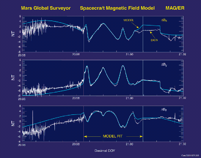
NOTE that special spacecraft maneuvers were needed before an adequate spacecraft magnetic field model could be developed. These maneuvers were executed in late 1999 and February, 2000 (HGA articulation sequences). The February 2000 maneuvers resulted in a model for the field of the HGA. The dynamic fields are still under study but a preliminary model is provided and used in the reduction of this dataset (July, 2000).
Spacecraft Field Estimation and Compensation:
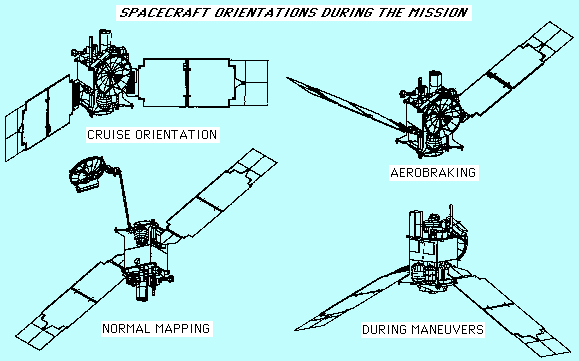
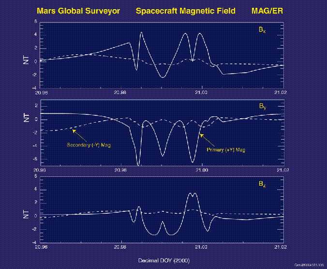
The spacecraft field estimation and compensation is a bit involved. The magnetometer measures the field due to all sources, the ambient field plus that of the spacecraft. The spacecraft may generate magnetic fields in many ways; the estimation problem is largely one of identifying correctly what on the spacecraft is responsible for the interference. It is usually very helpful to have specialized tests pre-launch to identify the prominent sources. Often one finds that it is impractical to operate the spacecraft in precisely the manner it will in space (e.g., powered by solar panels, power subsystem state, component articulations, thermal environment, and so on). Pre-launch tests of the MGS spacecraft identified permanent magnets on the High Gain Antenna (HGA) as the most significant source and sources associated with the power subsystem primary harness which were partially corrected.We categorize spacecraft sources as static or dynamic. Static fields are due to permanent magnetization, for example, magnets or magnetized objects. Magnetic fields are also produced by current loops, for example in power subsystems, solar arrays, batteries, and so on; these often scale with a known current and are called dynamic fields. For MGS, during mapping operations, the HGA is articulated in the frame of reference of the spacecraft (spacecraft payload coordinates, PL for short) as are the two solar panels upon which the magnetometer sensors are located. Each sensor also has an associated zero offset (for each range) vector which must also be estimated. Note that a spacecraft generated static magnetic field that is in the same reference coordinates as the sensor (sensor coordinates) will behave as a sensor offset.
Spacecraft maneuvers conducted in February, 2000 were very helpful in characterizing the static field associated with the HGA. Of course, since the HGA is constantly articulating, the "static" field of the HGA is time variable as seen by the sensors. These maneuvers were designed to map the magnetic field of the HGA: the sensors (and solar panels) were set at fixed locations and the HGA was rotated in elevation several times. The field of the HGA could then be determined from the difference between the vector field at the two sensor locations. The difference must be used to eliminate the time variable, and mostly much larger, ambient field.
A more complete model of the field at each sensor takes into account the possibility of a static field associated with the spacecraft and fixed in spacecraft pl coordinates (Bc), as well as dynamic fields both fixed in sensor coordinates (Bod) and fixed in spacecraft payload coordinates (Bcd). The former might arise from imperfect cancellation of current loops on the solar panels and the latter might arise from loops associated with power circuits fixed to the spacecraft body.
These sources are to be characterized in flight and on orbit about Mars. The ambient field is large (to 250 nT) and variable, all of which looks like very large amplitude "common mode" noise to our sensors (in this effort; the ambient field is of course most welcome otherwise). So we can only use the difference between the measurements to characterize the spacecraft field.
The magnetic field is modeled in sc payload coordinates (applies to both ib and ob sensors)
       Bpl = [ HGA ]  Bs   +  [ T ] Bo  + Ba + Bc
                           +  [ T ] Bod      + Bcd

       where Bpl is the field in cartesian payload coordinates,
             Bs  is the field of the HGA assembly, in cartesian
                 coordinates, in the HGA coordinate system;

           [HGA] is the transformation from HGA coordinates to
                 spacecraft payload coordinates.

             [T] is the transformation from sensor to s/c payload
                 coordinates.

             Bo  is the sensor zero offsets, constant (static)

             Ba  is the ambient field in sc payload coordinates

             Bc  is the spacecraft (body) field (static) in payload
                 coordinates

             Bod is field in sensor coordinates that scales with
                 the power system current (cartesian coordinates)
             Bcd is the spacecraft (body) field (dynamic) in payload
                 coordinates that scales with power system current

             Bod and Bcd are DYNAMIC spacecraft fields
                 we ASSUME they both scale with a spacecraft current
                 as follows:

             inboard  mag dynamic field scales with solar array
                 -y panel current;
             outboard mag dynamic field scales with solar array
                 +y panel current;

             Bcd, the spacecraft body field, scales with total current
                 (sao_i) output from the (shunted) arrays. This is the
                 current that goes into the power subsystem on the s/c
we use the observation Bpl (inboard) - Bpl (outboard)
to remove the ambient field. Pure sensor rotations will
constrain Bo, and coupled displacements/rotations (from
solar panel movements) or HGA articulations will be used
to constrain the spacecraft field Bs, modeled as an
offset dipole about the HGA origin.
A generalized inverse procedure is used to estimate the parameters of the various sources, e.g., the dipole coefficients of the HGA and the offset of the HGA source from the defined center of the HGA coordinate system; or scale factors (nT/A) for the x,y,z components of the dynamic field associated with solar panel current.
The current spacecraft magnetic field model (that used in the processing of this data) is described in sc_mod.ker, provided with this data release. It uses an offset dipole for the HGA (tests demonstrated that no improvement in the fit resulted from using a higher degree and order spherical harmonic), referenced to the HGA coordinate system (which is at the end of the HGA boom, see SPICE documentation). We found that no additional static spacecraft field was needed and so this is zero in the current release. The dynamic fields are at present imperfectly estimated but amount to about 0.2 nT/A or less in each sensor.
from mgsmag_ds_map.txt file as delivered to PDS

Courtesy of JPL

Larger version available
Courtesy of Jack Connerney

Larger version available
Courtesy of Jack Connerney


